First-Hand:The First CMOS And The Only Cryogenically Cooled Supercomputer

A brief history of the hardware technology developed for the ETA Systems ETA-10 supercomputer CPU and the major features of the resulting technology, many of which are applied to today’s systems.
Submitted by Tony Vacca, with input and editing by David Resnick
Forward
This document addresses hardware technical innovations that were a major contribution to the development of the ETA-10 in the 1980 time frame. The formation of ETA Systems within Control Data Corporation (CDC) and the demise of ETA Systems will not be detailed but brief commentary is provided.
William. C. Norris (CEO of CDC), Neil Lincoln (chief architect of the CDC Cyber-205) and Lloyd Thorndyke (CDC Senior VP) introduced the formation of ETA Systems to the world at the first National Symposium for Supercomputers in Los Alamos, NM before an audience of the leaders of large computer system developers and manufacturers including: Cray Research Inc., IBM, DEC, Unisys and others. The announcement took the audience by surprise and took most employees at Control Data by surprise as well.
It is noteworthy that ten years later, at the second National Symposium for Supercomputers which also was in Los Alamos, ETA Systems was the topic of conversation during symposium lecture breaks. ETA Systems had been terminated over a year prior to the second symposium.
The spin-out of ETA Systems was a resolution to a dilemma built up within CDC. Simply stated: CDC, after numerous attempts could not resolve the architecture differences between their mainstream Cyber hardware computer mainframe products and the CDC–Star or Cyber–2xx supercomputer products and the company could not afford two distinctly different organizations within it's dwindling budget. CDC observed the success of Cray Research Inc. in the supercomputer market and did not wish to exit this industry. In fact, CDC was encouraged to continue by key government clients. CDC decided to create a subsidiary funded initially by Control Data but eventually to become a spin-off company funded by public financing. It was a kind of ‘cake and eat it too’ scenario where CDC planned to reduce ownership across time.
Neil Lincoln quietly set up the first “headquarters” in an apartment adjacent to his and began planning the formation of ETA Systems, adding confidants to his organization as needed. Initial planning was completed prior to the Los Alamos announcement and at that time fewer than a dozen people knew of the formation plans.
Neil casted about for a name for the new subsidiary and multiple suggestions were considered. One evening, Neil’s son Sean suggested, possibly in jest, that the company should be named after ETAOIN SHRDLU, the printers devil. The first three letters stuck. Hence, the company became ETA Systems to the chagrin of many.
The initial employees who were asked to join were the nucleus of the CDC Cyber-2xx team located in the Advanced Design Lab (ADL) adjacent to the Arden Hills development and manufacturing facility. The ETA Systems team was already in place as it had recently completed the engineering and development of the Star-100, Cyber-203 and Cyber-205. Each employee who agreed to join was granted ETA Systems Inc. stock options as well.
After the announcement, the team quickly moved to a new facility in St. Paul Energy Park located approximately 10 miles to the south of ADL. Those who were selected for manufacturing and continuation had little to do initially while facilities were modified to fit the requirements in support of the design, engineering and manufacturing of large computer systems.
The facility in Energy Park was generously provided by St. Paul, MN in return for increasing employment promises. One-hundred employees and significant equipments was moved to the new facility, and walls, offices, meeting rooms, etc. were fabricated in accordance with the requests of the newly formed organization. Dedicated access to a CDC Cyber-205 supercomputer was also provided for hardware and software development.

Since the subsidiary was initially funded solely by CDC, great care was made by the newly formed ETA Systems executives to accommodate requests by CDC executives. One such request was to provide pseudo-security systems for CDC executives who had hunting and fishing cabins in northern Minnesota (a far cry from supercomputers). The executives surmised these small false—and functionally useless—security looking boxes having both a blinking light and antenna could be placed in the window of their vacant and remote cabins, and would potentially be a deterrent to would–be thieves. Now that was thinking gone bad, but…. Lloyd, the ETA Systems president, directed that while the facility was being organized upwards of 50 or so of these devices would be fabricated. ETA Systems first product !
In record time the Energy Park facility became operational and those responsible for development of hardware and software were busy at work. The executive contingent also began pursuing future funding. Reception to funding initially was cautionary considering that the company hardware was focused on cryogenically cooled integrated circuitry. A major concern by potential investors was the technology and only after a total technology failure by a start up company formed by the legendary Gene Amdahl— Trilogy—did ETA Systems get serious investment attention. The first two or three opportunities from external funding sources were promptly rejected by CDC. This was a confusing exercise: on one hand CDC spun out ETA Systems to relieve itself from a financial burden, but on the other hand it knew if third parties became joint owners they would lose their exclusive decision making clout. This issue persisted throughout the duration of ETA Systems and played heavily into the demise of the organization some 5+ years later and after ETA Systems had successfully produced a family of supercomputer products. Lloyd, as president of ETA Systems, fought energetically to free up ETA Systems from CDC control but eventually CDC replaced Lloyd with another leader and the demise accelerated. The irony of the ending was that on the day the doors closed, the sales and marketing organization had reached agreement to sell and deliver over 40 systems to a major organization in Australia. More irony was spewed when the US Government informed CDC (as there was no ETA Systems) that they were ready to purchase large ETA Systems computer products.
Some 6 years after the demise of ETA Systems the last operational cryogenically cooled ETA Systems supercomputer was powered down at the University of Tokyo and replaced by a Cray Research Inc. system. The first such system was powered down a few years earlier at Florida State University primarily due to lack of software maintenance support. The product was very successful; the necessary support by CDC to make ETA Systems a viable company was a complete failure.
All projects have a beginning
In the early 80’s Control Data (CDC) launched the Cyber-203 that was followed by the Cyber-205 supercomputer with modest success. The technology and logic teams then directed their focus to the next generation machine, internally designated the Cyber-2XX as I recall. System performance (primarily clock speed), cost and meeting the schedule were all key objectives for any system defined as a ‘supercomputer’.
- Speed Because Cray Research, under the guidance of Seymour Cray and Les Davis, continued to establish industry performance standards and objectives for supercomputers with both the Cray-1 followed by the even more impressive Cray XMP and Cray-2 multiprocessor systems.
- Cost Since supercomputers were extremely expensive, typically in excess of $15 million dollars per copy. This restricted the customer base considerably.
- Schedule Since prior CDC supercomputer developments had established CDC as a very delinquent company.
Initial Hardware Technology Plan
A conventional, proven and evolutionary approach for integrated circuit (IC) logic was initially selected for the Cyber-2XX system. Circuit technology selection was crucial since it directly influenced performance parameters and central processing unit (CPU) cost . It established, within the logic design team, a set of guidelines to design within, including pins, logic gates types, gate area and power, device layout and ultimately, performance goals. The circuit selection also determined boundaries for the size, power and packaging for the resultant design.
Motorola Semiconductor, with considerable prodding, agreed to launch an 8,000 gate equivalent Emitter Coupled Logic (ECL) gate array for CDC. This was the then circuit technology of choice for high performance computer CPUs. They would apply their newly developed IC processing capabilities (MECL-3). A key stipulation imposed by Motorola was that Control Data circuit design resources must be involved in the actual gate-array development. The previous generation ECL gate array developed by Motorola in concert with Cray Research Inc. had a gate capacity of 2,700 gates. This gate count was a considerable increase over their previous developments. There were insufficient customers at Motorola to commit their critical new process design and application resources to what might well be well a relatively small market. Motorola, after agreement to mutually apply resources committed to the effort and their impressive advanced ECL processes, established a formal program directed at the CDC-based design. (This in itself was a major accomplishment since providing processing information to third parties prior to announcing a product was seldom done.) At the time, the only viable competitor to Motorola for high performance logic devices in the IC industry was Fairchild Semiconductor. Although Fairchild IC processes were equally impressive, they would not commit their fabrication resources nor their manufacturing capacity to a gate array. They chose, instead, to commit resources to a family of predesigned ECL chips (F-100K as I recall). Motorola would process the chip set on their advanced bipolar manufacturing line and Control Data would design the master chip and chip-set within processing and design layout rules provided by Motorola. I must add here this partnership would have not been established if it were not for a long-term relationship between key individuals of both companies for more than a decade prior.
Logic designers at the CDC Advanced Design Laboratory were given preliminary design rules based on computer device models, estimates of gate per chip densities and pin allocations. The technology was titled HP for ‘High Performance’. There was a ‘natural’ follow-up period of grumbling by logic design team members led by very experienced and innovative folks (Ray Kort, Maurice Hudson and Dave Hill to name three), but circuit designers had learned to accept this since logic designers traditionally found the circuitry submitted by the circuit group was always too slow and contained insufficient quantities of gates and pins (I/O ports) per die. Once this ‘traditional’ critique was completed, the logic design team provided required and necessary direction and valuable cooperation. Basic building blocks were defined by the logic designers including gate functions, register (intermediate storage) functions, etc. From this set of preliminary rules, higher level function blocks were defined and capacity per reasonably sized printed circuit (PC) boards defined. Based on these efforts the initial design of the Cyber-2xx using essentially the Cray Cyber-205 based architecture was launched. From these technology limits, HP technology, including circuitry, packaging, power consumption, system size, and hardware cost, were established.
In parallel with this effort, and in the same design group (circuit, packaging, PC board and newly formed CAD tools for layout and design of chips and boards), chief chip design engineer Randy Bach was assigned to develop an advanced CMOS gate array chip for the CDC Canadian computer development organization who were pursuing a CMOS was in its infancy and being used almost exclusively for memory devices, low performance peripheral devices and low performance microprocessors (5 to 10-MHz clock speeds). The breakthrough CMOS gate array chip design featured 5,000 gates plus appropriate I/O communication devices. Gate arrays for CMOS were also nearly non-existent so Randy and his small team of associates developed the cell library, chip clocking scheme and total chip layout. A cooperative relationship with the CDC Canadian development team to meet their unique objectives was as well. The technology—CMOS—was selected for its superior cost advantages at the expense of considerable lower performance over the HP alternative. The name for this gate-array design was HD for High Density. This differentiated the two projects: HD for cost performance and HP for high performance.
The HD effort was developed completely separate from the bipolar ECL based gate array (HP) to be used for the next generation supercomputer. Both HP and HD were being developed by the same organization within ADL. At the time it was intuitive that the two projects could not be merged given the vastly dissimilar objectives. One design was addressing cost, low power consumption and size and cost reduction while the other design was addressing ultimate processor performance which resulted in considerably higher power consumption and considerably higher costs.
The CMOS design effort progressed impressively and eventually the effort responsibility was transferred to the Canadian Division. Throughout this effort Randy became increasingly intrigued by CMOS technology for its logic design flexibility, circuit packing density (area required per logic function) and reduced power consumption. Circuit capacity was achieved because defining a logic or Boolean function required less overhead circuitry with CMOS than with ECL, TTL or another bipolar circuit configuration. In CMOS nearly every component is put to Boolean use!. Power reduction for CMOS was achieved by utilizing circuitry that consumed power only during the time interval when the circuitry was switching logic states (“0” to “1” and “1” to “0”). The performance gap between CMOS and high-end bipolar technology however, was greater than 20:1. CMOS performance was tied directly to the limits and opportunities of photolithography technologies, which defined ‘gate length,’ while bipolar transistors performance was tied to third dimension diffusion and implantation depths which were much smaller and could be fabricated more precisely than minimum photographic capabilities. Projections for CMOS technology, for both logic gate capacity and performance were attractive, but designing for the next generation based solely on these projections and the semiconductor industry supplier participation was not only too risky but seemingly foolish when CPU performance was the ultimate objective for supercomputers. At this time, CMOS had no ‘industry drivers’ for high performance applications, and computer industry circuitry providers were not receptive to this market as well.
There was concern for the IC industry lack of priority visibility for future ECL bipolar technology beyond the Cyber-2xx development timeframe as well. Power estimates were increasing and processing projections for required performance of new designs was not improving at a favorable rate. The Cyber-2xx was safe, but then what?
To be certain of the assumption that CMOS was not a prime time technology for the present development cycle of supercomputers—the Cyber-2xx—a supplier evaluation trip was made to the west coast (Silicon Valley) where David Frankel, Nick Van Brundt and I met with leading CMOS product developers. We found those involved with CMOS technology focused on products primarily for cost-performance storage, game-boxes for television and toy markets—hardly supercomputer technology we surmised. We were impressed however with both the circuit density and memory storage capabilities of this emerging technology. And with each generation of increased storage capacity, the circuit and resulting system performance increased while cost per data-bit was reduced —a wonderful ‘cake and eat it too’ characteristic of CMOS IC technology. The technology also was impressively supported by new design enhancement tools and a new and emerging market of ECAD or Electronic CAD tools for both electronic circuit designers and also logic designers. The concept of The Long Thin Designer was in its infancy. By using that developing methodology, CAD tools would provide logic designers a much more direct path to the physical chip, thus reducing the complex capabilities required of circuit designers including fully manual layout of logic functions. David, not being a circuit designer per se, was impressed. I was appalled. After all, a good part of my career was spent as a circuit designer. Were circuit designers going to become obsolete? The thought was revolting :-). It took over a decade for a fleshed-out form of this concept to be realized by the design community. The resultant methodology did include, as it turned out, circuit designers too, but they increasingly resided in the IC industry while circuit designers for user-level functionality and system development were primarily used to support the CAD and logic design groups as well as data transmission and power designs. Additionally, Nick noted a major issue was on the near term horizon, that adequate testing of these increasingly complex and increased pin devices. IC chip testers requiring one pin per IC chip port would be a challenge from just a physical proximity consideration. He began exploring alternative methods to insure functionality using conventional and lower pin-count testers (fewer test pins than a pin per I/O port).
At this same period Cray Research Inc., the supercomputer industry leader, was using bipolar circuitry based on two logic gates per chip for the Cray-2 and beginning prototype development of their next system (Y-MP) using approximately 2,500 gates per chip. It was clear that despite the vast increase in gate capacity and the reduced power consumption realized by using CMOS technology, bipolar ECL technology was the technology of choice for the Cyber-2xx. Performance dictated this decision.
Design and Architecture get into the mix
It was customary for Neil Lincoln, the supercomputer chief architect; Dale Handy, the supercomputer manufacturing manager; and me, the circuit, memory, packaging and CAD leader to go off-campus for lunch every eight to ten days to discuss progress and issues at either Arthur Treacher's Fish & Chips or Zantigo's fast food restaurants (not high class, but a match for our personalities). As a side note, both of these fast food places disappeared during the brief duration of ETA Systems. Zantigo's returned (I think because they knew it was safe as the three of us cannot patronize their establishment together any longer. Neil unfortunately passed on a few years ago: I currently live in Arizona and Dale still resides in Minnesota).
Neil spoke very clearly when he was bothered. At one of the Zantigo’s luncheons he was extraordinarily clear. After two years of very successful development progress with Motorola and now entering a demonstration phase of a state-of-the-art bipolar next generation LSI chip and one that was at least two years ahead of the rest of the universe as we knew it to be then (including innovative Japanese technology), Neil exposed a fierce HP technical critique. The chief architect (and much more) stated the following: The state-of-the-art bipolar HP chip design had insufficient gates-per-chip and the pin-to-gate ratio was insufficient. Furthermore, the next generation computer should have a single board processor and not a multiple board CPU. And, for frosting on this already over-baked and burnt cake, Neil added the present chip consumed too much power, was impossible to test and, by his analysis, would result in a much higher product cost than required. Other than that Mrs. Lincoln, how was the play? Was this a point in time to argue? Hell no. He knew architecture, we trusted that without question. I was supposed to know technology. This was merely the demand to elevate the technology-bar by another factor of two or so. Did this proclamation come with a few alternate solutions/suggestions? Not at all. It was my job to fill in the blanks!
During this discussion, Dale was really wise. He said not a word, pulled out his overstuffed wire wound note book and jotted down a few tidbits—things he never shared until either Neil or I misquoted a recollection of the meeting, oftentimes some months later. What else was in that book? I never knew but it always seemed stuffed. Oh, Dale ate his meal and kept quiet too.
Now I had already learned that responding with “That is not possible!” or something equally trivial was futile. So what if I was the leader and guru of circuits and knew (or thought I knew) more about circuit technology and the status of the IC industry. The facts for our HP efforts were just revealed to me: There were too few gates than required for the machine that would follow the Cyber-205. End of discussion.
When I replied “OK,” Neil, although taken aback since I think he really did want a bit of push-back, did not ask for new direction he was patient (tongue now in cheek). He indicated we would meet again next week, and since this meeting was on Friday and the next ‘noon luncheon’ would very likely be Monday—I had a lot of time—at least based on Neil's 24 hour work clock.
The logic designers and perhaps a dose of frost on the brain had gotten to him I quietly surmised. Schedules, of course, could not be altered, and… that was that. In an attempt to soften the blow he smiled and bought lunch: three Cokes and three combos. Neil's combo was a large order. The trip back to the lab was quiet. Fortunately the trip was brief as our ‘gourmet’ eating establishments were all very close to the lab.
The messenger of bad news
Having little time and a major task ahead, that afternoon, key design team members were assembled; I might miss one or two but Randy Bach (leader of HD), Doug Carlson (leader of HP), Dave Resnick, Bill Berg and John Ketzler were those that I recall now. Doug was a mechanical engineering leader. To expand his experience and because of his management skills Doug was assigned to be the Motorola HP project leader—an assignment he probably never forgave me for. John was the key circuit engineer on the Motorola project primarily assigned to the task of on-chip clock distribution and skew minimization. Dave was (and still is) a very versatile innovative, well-read and perceptive engineer and architect. Bill was a mechanical design expert and innovator and Randy brought his CMOS experience having successfully completed the design and validation efforts of the impressive 5,000 gate CMOS array for the Canadian division.
After I stumbled through the essence of the recent luncheon meeting emphasizing that all efforts on our HP program were about to cease, we moved toward filling the design void. A clean up activity was to inform Motorola and the team. Doug and I concluded we would jointly inform them of decision not to continue. I thought it was a nice gesture to share that awful event since I previously stuck Doug with the project in the first place. The team would package-up what was accomplished and turn it over to Motorola to carry the ball forward if they wished.
As a side note, Motorola and Cray Research Inc. did continue the IC gate array design. It was used by Cray Research Inc. in the Cray C90, a very successful Cray Research supercomputer whose development was led by Steve Nelson and with the circuit leadership of Mark Birrittella.

The meeting then turned to what were the next steps.
The key challenges that were outlined were:
- IC Technology that could meet the new lofty goals
- The PC board technology required to meet a single board CPU goal. For this we called in LeRoy Beckman, the methodical leader of the PC board development efforts.
- Packaging and interconnect technology required to support the two above requirements. For this Carl Breske (key innovator), J.C. Olson (Packaging engineer) and Bill Berg (innovative mechanical designer) joined future conversations to add their experience and creativity.
- CAD technology necessary to accurately design IC and PCB technologies. For addressing this topic, Dr. Howard Krohn, Paul Dukart and Jerry Buldoc were added. Both Howard and Jerry eventually left the company, not for this reason, but to pursue other personal goals. Folks like Paul Dukart, Hope Bauer, Doug and Becky Kempernick, John Doyle, Jim Bailey, Jim Kreilich and others took over the CAD leadership and accomplished outstanding work.
- Suppliers for the IC technologies listed above: Did they exist? The assembled team did not think so. It was a one-off development to complete the 5,000 custom gate array and suppliers were reluctant to take on new CMOS efforts for a small market return.
- What additional internal resources were required to achieve objectives?
- System packaging beyond a single CPU (memory, peripherals, I/O, etc..) Again Carl and Bill were asked for ideas.
- Testing of complex IC and PCB technology. Here a totally new path to testing complex circuitry had to be developed. Nick Van Brundt and Dave Resnick addressed this with novel and impressive results. Nick left Control Data to co-found a company dedicated to use the principles developed for this effort. Dave accepted this challenge, gathered the ideas of Nick and adapted them to the design team of the Cyber-2xx to include the principles of chip self-test as a feature within the chip itself thus reducing complex test equipment while insuring design functionality. This single feature permitted the design of large chips to be successfully fabricated, tested and validated on the system. This is elaborated on later in this document (See ‘B.E.S.T.’ in the design summary) Often overlooked, this single feature played key roles in the success of the chip design and CPU manufacturing validation including the validation and test of the interconnect of multiple chips at the same time.
Time elapsed, and a new effort began to evolve after a series of experiments, studies and a prognosis of technology trends based on projecting near-term technology out to the required time frame of the Cyber-2xx. This was all accomplished without formally informing the CDC leaders that HP had been abandoned. Why? The most obvious reason is that no program should be discarded without an improved solution being proposed (the exception being the Chief Architect, of course).
The next task, once a technology suite was selected, was to inform all participants of the termination of HP and get agreement from the overall leader of the supercomputer effort: Lloyd Thorndyke. Now put yourself in the shoes of Lloyd for a moment. A technology leader appears at his door with an alternative approach:
- Discard the two-year effort with a premier supplier of high performance circuitry (Motorola) and associated HP packaging.
- Use a technology—CMOS—that was 5 to 10 times slower in performance. We were going to build a state-of-the-art supercomputer that would be competitive when we completed the project—just as long as it was cooled at minus 300 degrees and quadrupled the gate count of the recently developed HD CMOS chip. At that time we did not have a clue this could be accomplished. Well, that is not completely true, there was Moore’s Law floating around the industry stating the number of components could double every two years or so. This scaling was directly proportional to performance enhancements (Dennard scaling), ergo the performance would double as well. Therefore, it followed that in 4 years the present 5,000 CMOS gate logic chip would be 20,000 gates and, and the present CMOS gate array operating at 40 nsec would operate at 10 nsec. Now by merely super cooling this projected technology to 77 degrees Kelvin, the speed would double or more to 5 nsec. This was just perfect and a “piece of cake” to achieve, except there were no known manufacturers even considering CMOS gate arrays. Even the 5,000 HD gate array was a custom project designed by CDC.
- Design the entire processing unit on a single board. But, the industry could not build this type of board nor did they want to. Oh! Let’s add that we calculated it would be about 0.7 miles of embedded interconnect for about 20,000 wire connections on this single board, which was a very considerable length and connection count for at this or any timeframe.
- Reduce system manufacturing cost by part count reduction (with parts that did not exist at this time).
- Meet the objectives and schedule within the existing budget, headcount and expertise.
The team left the task of explaining this half-baked plan to me. After all, they had a few things to do. Lloyd actually listened. Did he ask questions? You bet he did. At the end of the discussion he agreed we could, as vaguely planned, proceed. But he did ask that I ‘stop by’ more often with updates—a lot more often. How many leaders would have said yes to this? For certain Lloyd was the only executive in CDC, and I was fortunate enough to be reporting to him. Also, Lloyd was extremely technically competent. His basic understanding of stated objectives and having a respect for the concepts presented were valuable and instrumental in his decision. Bottom line: The team was given permission and support to proceed on this aggressive development.
Results
Before reviewing the details of the decisions as well as how the ETA System technology kit was developed, key noteworthy accomplishments are listed:
- First industry high performance CMOS CPU
- ETA Systems selected CMOS IC technology for high performance supercomputer CPUs in 1984. It was not until at least 10 years later that high performance processors used CMOS ICs. This included: IBM, Cray Research Inc., Fujitsu, Hitachi, and NEC. Until then conventional bipolar technology was the CPU technology of choice with one exception; The unsuccessful attempt of SRC Computers to use GaAs IC technology.
- First industry single board supercomputer CPU
- This was enabled, in part, by the chip density (gates-per-chip) as a result of advanced CMOS, the use of layout and design CAD tools for optimum layout and simulation, the successful design of a 45 layer advanced printed circuit board (you read it right: 45 layers) together with innovative chip attachment and cooling and combined with other engineering efforts. The result was a single processor containing 139 chips, totaling 2.7 million logic gates, to be packaged on a single board.
- First built in self-test computer
- First industry supercomputer system to be designed with a self-test CPU processing unit of the 2.7 million gates each were validated for functionality and performance in less than 4 hours. Interconnect errors were recorded and chip-tochip interconnect flaws were corrected in minimal time. Any failing chip was flagged for replacement, though only fully validated parts were assembled on processor boards. Competitive CPU checkout during this same period required weeks to months. Incoming acceptance testing and performance sorting of the logic IC Chip (function and performance) also used the same self-test innovations. Necessary tests were completed in less than a minute, often only a few seconds. The test capability also was used in the field, though the capability to replace failing chips or broken on-board wiring on-site was not reasonable. This seldom was required due to the high reliability of the IC and chip-to-board assembly in manufacturing. Self-test also enabled detection and resolution of occasional connector engagement failures during assembly.
- First industry production LN CPU (and the only system to date)
- The ETA Systems CPU, housed in a cryostat, was immersed in liquid nitrogen (LN) at 77 degrees Kelvin (minus 300 degrees Fahrenheit). This improved performance by more than two times greater that of CMOS technology operated at room temperature of 300 degrees Kelvin.
- CAD USAGE
- First system at CDC to fully utilize CAD software to design chips, boards, validate the logic design and incorporate built-in diagnostic testing of the system with synergistic tools permitted checkout of a CPU to be completed in less than 4 hours. Manufacturing costs were significantly reduced from previous products. This technique, by providing each CMOS chip type a test result, was also used by the IC supplier thus greatly reducing the complexity of the IC supplier’s probe test hardware and software.
- Multiple Price Points
- First industry system to have multiple price point products from a single design. The performance range of the ETA System products was 27:1. This was an 8 processor system operating at 7 nanoseconds clock period down to a single processor system operating at 24 nanoseconds. Processors were manufactured, tested and validated from a single manufacturing assembly line using identical test devices, tooling and techniques. IC Chips were performance sorted using B.E.S.T. (built–in–self-test described later). IC chip sorting began at incoming inspection.
Technically, even higher performance devices using these technologies were possible by altering the process to optimize functionality at 77 degrees Kelvin. By doing so however, the same chips would not be functional at 300 degrees Kelvin or room temperature. Sacrificing some performance improvement at the cryogenic temperature permitted CMOS functionality at both cryogenic and room temperatures. The decision to permit this wider range of CMOS functionality was made after considering product development options and proved to be a wise business decision.
Boring into details
Any ‘technology kit’ must be driven by customer need. In the case of supercomputers the craving for increased computer performance at a lower overall cost was the deciding factor to pursue circuit and packaging technology emphasizing high speed. In any supercomputer company a combination of marketing requirements (customer demanded features), architecture innovations and logic design demands dictate the initial objectives of the hardware circuit and packaging organization. CDC, by contrast, had Neil to interpret what the ‘customer needs’ were. Neil was the customer and between Neil and the logic design team the ‘needs’ were defined for the circuit, CAD, and packaging organizations, in other words: the technology kit. I state “initial” since once the objectives are digested and key technologies are evaluated for the time frame addressed, compromises are the norm. In the case of ETA Systems technology selections in the early 1980s, this was the strategy implemented.
Integrated Circuit selection
The objectives, listed in earlier paragraphs, were first integrated into the architecture and logic design requirements. A technology market survey of key integrated circuit suppliers was conducted with emphasis on what was in development and planned for product introduction within a 3 – 4 year period from development initiation, not what was available at the time of the survey. A risk assessment was then made. Primary focus was on the most dynamic technology, which was the selection of the IC circuit technology. All decisions as to volume requirements, pins, packaging, etc., resulted from what was determined by this survey and the accompanying risk analysis. Merging the logic design objectives including gates, bandwidth and performance of key functions was next.
As stated earlier, an ECL high performance bipolar gate array using Motorola advanced IC technology had been selected initially.
Logic cell libraries were agreed to that were acceptable for Motorola for the general market and to CDC for the CDC logic designs). Pin counts (for power, ground and input/ output interfaces) were established and power consumption estimates were made. Once these parameters were established, board size, power systems and thermal management controls were evaluated in a trade-off give-and-take. Features of printed circuit boards: line widths, spacing, interconnect vias and number of layers were compared to the board size capacities. Laminating press capabilities, drill designs and printed pc board processing limits were also included as part of the overall definition. IC packaging, limits including minimum size of package, pin spacing, heat removal, etc., were evaluated in parallel with PC board limitations.
The chip design began with confidence based on the successful test vehicle results explained in Addendum 1. In that design effort a gate array, functional logic elements and PC board were successfully demonstrated, being designed and implemented totally using computer aided design software developed by the Advanced Design Lab. Most of this knowhow was used in the development of the Cyber-205. Now the design was being asked to develop IC technology, not with 100+ gates per chip but with 8,000 gates per chip. The HP (High Performance) technology would be used.
After a careful and critical review, Neil Lincoln, the chief architect, rejected the design. This was covered in the introduction. Three key reasons were sited:
- performance would be impacted due to the 8,000 gate limit. This was because worst-case logic paths based on Cyber architectures could not reside in a single chip as chip-to-chip crossings and physical distances would increase the clock period,
- Power consumption per CPU, although lower on a performance ratio basis to previous generations, was too high when the total system size, including the multiprocessor objectives, were considered;
- system cost also was prohibitive. Cost at this juncture in the design process is always a subjective issue but nevertheless a key design component.
Reliability for large systems was also a concern since the pin-count per CPU, although significantly reduced from previous discrete component designs, remained high.
The bottom line was that the HP technology kit would not be competitive when the Cyber-2xx was introduced in four years. This was very subjective—but someone, Neil in this case, made this monumental decision and although there was no alternative IC technology visible, HP was not an acceptable technology. We were aiming too low.
Back to the drawing board
Bipolar technology has variants that enable conventional NPN and PNP transistors to operate in a non-saturating mode by not allowing the base voltage to be higher than the collector voltage, thus biasing the collector-base junction. By not saturating the operating transistors switching characteristics are improved, resulting in preferred balanced 0-to-1 and 1-to-0 transition times. In addition, the non-saturating ECL circuitry provided true and compliment outputs for each logic function: both AND/NAND, OR/ NOR, in addition to latches and flip-flops ,also had true and complement outputs. This provided a major advantage: a reduced number of gate levels of complex boolean functions (add units, multiply units, instruction decode units, etc). Under the category of ‘no free ride,’ non-saturating ECL circuitry consumed higher power than the more popular but much slower saturating logic circuitry (TTL or transistor-transistor logic). Other improvements in performance for integrated versions of ECL logic circuitry included replacing conventional P/N junction isolation between circuit devices on a single die with oxide isolation between circuits. This results in lower capacitance per circuit which greatly reduced charging and discharging current when logic levels switched. ECL also had minimum power buss transients during switching because of true and compliment switching simultaneously resulting in advantages to power related noise generation.
Complementary Metal Oxide Silicon (CMOS) technology, especially during the development time period of ETA Systems, was a simpler and more efficient logic circuit. This form of logic also had a simpler manufacturing process. Stacking of P-channel and N-channel transistors in series between voltage bus rails defines a single complementary gate. Functionality of the logic devices is much more forgiving to process variations due to a larger voltage swing and only active transistors used to define the circuitry. This is because resistors, diodes, etc., are absent and no additional overhead circuitry is required to define necessary threshold levels as required by ECL. The physical size of a logic function when compared to a bipolar equivalent is significantly smaller, resulting in an increase in logic functionality per unit area. CMOS technology also consumed power only when the circuit was switching, so power (P) consumption was directly proportional to the frequency (f) it was operating as shown by the expression: P = C x V2 x f. ECL circuitry, by contrast, consumed approximately the same power whether switching or in a quiescent state. Later forms of CMOS, especially those designed in early 2000 and beyond, had increased power consumption primarily caused by increased bulk leakage currents as a result of processes developed for lithography having features smaller than 90 nanometers. Technology at the time of the development of the ETA supercomputers had minimum features of 1,200 nanometers. (In 2009, by contrast, the production capability was approximately 25 nanometers.)
Advantages to using CMOS were obvious:
- More circuits per given chip area,
- Lower power consumption and
- Higher functional yield. It is important to stress functional yield. CMOS devices function over a much larger range of processing variations (>50% vs. 10 to 20 percent for ECL). This wider range of functionality yielded for a given process rule-set (at any given generation) provided in excess of 200% performance variations for CMOS vs. 20% to 30% for ECL. This was a major reason that CMOS devices were sold at a much lower performance than any bipolar counterpart. In other words, if the product is specified to accommodate all functional good parts in each processing lot (wafers processed at the same time) and without consideration of performance, more CMOS IC devices are functionally yielded from each processed wafer.
There is one other key difference in defining performance for bipolar and CMOS devices. For ECL (or any other bipolar device) the maximum transistor operating frequency is defined, in part, by the base width: the physical distance between the emitter and collector of the transistor located in the third dimension (thickness) of the semiconductor. This is determined by the spacing based on diffusion or implant of the emitter and is controlled in the vertical direction of the semiconductor device or chip and limited by process control that is quite precise. This implant distance can thus be very thin providing impressive high frequency performance since the maximum frequency is inversely proportional to this resulting base width. For CMOS the gate length, the distance between the source and drain implants, defines the critical performance parameter. Gate length is defined by mask photolithographic limitations for any generation of processes (located on the surface dimensions).
Bipolar devices in the 1980s and well into the later half on the 1990s, therefore had higher operating maximum frequencies than their CMOS counterparts. As capital equipment primarily optics to generate masking and etching capabilities-defined smaller and smaller geometries, performance improved dramatically for CMOS technology. Also advanced techniques using new equipment and processes—too many to discuss in this paper—providing CMOS with even more impressive performance increases. This was accomplished at the expense of process complexity and did not exist during the period of the development of the ETA-10. This was a result of smaller gate lengths but also each generation had smaller devices resulting in lower capacitance loading which resulted in reduced time constants therefore enabling faster logic state changes. During the time of the ETA Systems supercomputer development, CMOS technology had not achieved the performance advantages bipolar devices could realize.
The potential for future improvements, as stated above, were on the horizon and projections clearly indicated by the second half of the 1990s (nearly 10 years after the first ETA Systems supercomputer would be available), CMOS would overtake bipolar in the last and most important supercomputer parameter: performance. To restate this: The IC industry was transitioning to CMOS technology and more development funding at the device and equipment level was being expended to accommodate new markets focused on the potential of CMOS than was being invested to improve bipolar devices. This was because CMOS was less expensive to manufacture, was already accepted in the large memory storage market, and most applications did not require the performance levels sought by the much smaller supercomputer market.
Bipolar technology was stretched to a practical limit for the time frame in question. ETA Systems was fully aware that the IC industry was entering a technological transition period. Neil, with his declaration that the most advanced bipolar technology available was insufficient for the next generation supercomputer, forced the CDC technology decisions to investigate elsewhere.
There were two technology candidates to investigate: CMOS with its impressive circuit packing density and GaAs with its superior raw performance. GaAs was discarded for two fundamental reasons: the IC industry was not financing developments of this technology for high density devices nor was there wide spread interest to produce GaAs in high volume.
To be fair, Mr. Cray at Cray Research Inc selected a very low logic density chip and developed an extremely high density packaging (3D modules to package the relatively high power devices) as the technology kit for the Cray-3. After a significant development effort (both time and dollars), which included relocating to an entirely new venue in Colorado Springs, Co. and creating a new company—SRC Computers—the GaAs effort was abandoned.
The IC industry, therefore, had only one other technology candidate, GaAs, which was, in 1983, used exclusively for lower cost and considerable lower performance applications and memory device technology where more bits per die could be fabricated at the expense of lower performance than that of bipolar counterparts. The impressive characteristics of CMOS technology at this time were lower power consumption per function, smaller size per logic function and lower cost per die. The lower cost was realized due to two key factors: the smaller physical size per function resulting in more logical functions per unit of area and higher chip yield due to the reduced number of processing steps to generate CMOS devices with a wider functional range of operation. That was the good news. The concern was system performance. While bipolar technology had set the standard for clock periods of 10 nsec for supercomputer architectures such as the ETA System projection, CMOS was at least 5 times slower, and in most cases 10 to 20 times slower for equivalent architectures. Based on this parameter alone, CMOS was not a candidate for supercomputers in the 1990 – 1999 time frame, the time frame where the ETA Systems supercomputers would be in high volume production.
The next steps for CDC (recall that at this time CDC still had a supercomputer division) were dramatic and at times emotional. First, the team had to discard the ECL design and terminate the effort with Motorola. This was very difficult since both companies depended on each other for this design and secondly, all objectives of the ECL product were being met within the specifications established. Motorola Semiconductor was an excellent supplier and a long term relationship had been established with both their development and manufacturing organizations. This was a difficult divorce for all parties. The CDC team, which later became ETA Systems, provided Motorola with all of the design details to date. Considerable effort was made to insure that the program was successful at Motorola.
Next, a full-effort evaluation of all technology candidates occurred. CMOS futures were explored in depth. Alternative ECL (bipolar) candidates were also considered. CMOS was viewed as the technology of the future but the future was beyond the time frame necessary for product introduction. CMOS was selected despite open ridicule and skepticism by management in other CDC organizations. As kudos were handed out later by many, no one gave the credit due to those who risked the viability of ETA Systems Inc.: the CEO of ETA Systems Lloyd Thorndyke and the chief architect Neil Lincoln.
Key events leading to the use of CMOS technology
Moore’s Law (defined by the renowned innovator and co-founder of Intel, Gordon Moore) projected IC technology (CMOS) technology, would double in density every 18 months to two years. Dennard scaling indicated the performance would double as well. The ‘law’ has become a self-fulfilling technology projection and thus has been accurate for CMOS technology for the next decade plus of technology growth. To achieve the chip density increase and associated performance increases predicted, multiple advances had to occur:
- Features on the chip (metal widths and spaces to interconnect devices and actual device parameters) would be reduced every 18 months to 2 years, thus doubling gate count for the same area.
- The die size would increase (more gates per manufactured chip above a simple gate density increase). A major side effect of this, taken along with the density increase, is that the number of metallization levels (used for power distribution and interconnect) would have to increase.
- The technology would gain broad industry popularity. This would mean required capital equipment investments would keep pace with the ‘law,’ and new and better applications would be brought to the market thus increasing volume and lowering cost. This suite of benefits would drive CMOS technology; the relatively small supercomputer industry, by itself, could not drive such a large and emerging industry.
Noteworthy industry activities at this time:
- In CDC, the Advanced Design Lab investigated operational performance improvements by operating CMOS technology in a cryogenic environment. Several ring-counter configurations generated previously using a 5,000 gate test-chip discussed earlier were dipped unceremoniously into a liquid nitrogen thermos jug expecting to witness the shattering of the silicon and the detachment of the solder joints. Wires were attached to a remote oscilloscope to witness any change in operating frequency. Not only did the CMOS chip withstand the harsh environmental change, the frequency of the ring oscillators doubled as calculated. The mini-system operated for weeks until we discontinued the experiment, concluding it a success. John Ketzler, John Olson and John Fox grew tired of refilling milk cans with liquid nitrogen from the source at a nearby CDC reliability facility. Analytical analysis applied to the silicon design validated the research previously conducted by others, namely IBM and the University of Arkansas and now it was confirmed at CDC.
- A key US Government agency, the DoD, sponsored an IC technology acceleration program focused on advancing CMOS technology: the Very High Speed Integrated Circuits (VHSIC) program. Specific direction was provided the Army, Navy and Air Force. This certainly captured our attention.
- Honeywell Semiconductor, one of the participants in the VHSIC program held a technology luncheon IEEE symposium in which they presented an impressive and state-of-art 11,000-gate CMOS development effort. Attendees from CDC were impressed, especially a key designer, Randy Bach, with the efforts. The chip was certainly larger than any that had been developed to date and the performance was accelerated beyond what was predicted for the 1988 time frame by the conventional IC industry. Honeywell was a major recipient of one of the VHSIC contracts. Honeywell also had a development operation in a nearby Twin Cities suburb and was completing the fabrication of a huge (for that time) manufacturing facility at the base of Cheyenne Mountain in Colorado Springs, Co.
- Logicians and architects at CDC, led by Neil Lincoln as chief architect, Ray Kort, Maurice Hudson and Dave Hill and others, determined that a minimum useable gate capacity of 15,000 gates per die would allow them to achieve a key objective: that of having a worst-case register-to-register path reside within a single chip.
- The logicians wanted long integer addition (at least 48 bits and preferably 64) to be done in a single clock period. This allowed things like address arithmetic to be done optimally, and the number of gates in the longest path of that logic was similar to the long paths of other important functions. The total delay for the logic and the loading and wiring delays for that path set the objective for the clock period. The number of gates in several major functions, such that there were no chip-to-chip crossings, set the desired number of gates in a logic die, when using the set of logic macros that were planned.
- During the project a few special macros were developed. A re-sync macro was done to support interfacing between different clock domains and a macro was done for the multiply logic to speedup partial-sum reduction logic and thus both speedup and reduce the size of the multipliers.
- Research into technology experiments uncovered significant performance attributes of CMOS technology:
- The technology was functional across a wide range of voltages and temperatures.
- Performance for a given generation of CMOS could be significantly altered.
- The higher the operating voltage (within semiconductor constraints, of course) the higher the resulting performance. However, with increased operating voltage power consumption, although significantly lower than any alternative technology, increased as the square of the operating voltage.
- The lower the operating temperature of CMOS the higher performance as well. This factor was studied by others and carefully documented from 400 degrees Kelvin (100 degrees above room temperature) to a low of 77 degrees Kelvin. (77 degrees Kelvin is the boiling point temperature of liquid nitrogen.)
Summary of what was learned with this study
- CMOS IC chips currently (four years before the need for an ETA Systems product) had a capacity of 11,000 gates.
- The performance of these gates, when operated at liquid nitrogen temperatures, would perform at least two times faster than at room temperature.
In addition and in parallel, the following technology specifications were established:
- 15,000 useable gates were required per chip to meet logic designer chip boundary requirements. If Moore’s law was applied to these parameters, within the time frame required, it was possible to achieve both gates-per-chip capacities and performance goals when the system operated in a liquid nitrogen environment.
- The IC industry by now had established a metric to use CAD tools for gate or cell array designs, vs. hand layout of required functions which would be difficult to validate prior to committing to silicon. A major effect of this was that an additional 20% to 30% more gates (or more die routing area) in a gate array were required to enable functional and performance sensitive placement and routing because of CAD limitations. This meant if the ETA supercomputer required at least 15,000 useable gates to accomplish necessary designs based on its architecture, an 18,000 to 20,000 gate capacity per chip was required.
- There were at least two IC suppliers, Honeywell and TRW (both had VHSIC contracts with the US government) who were pursuing CMOS as a performance and high gate-per-chip capacity technology. Both were interested in encouraging participation by other third party users. IBM and Intel also were working feverishly at optimizing CMOS technology but were not offering access to third parties.
- The chip size was restricted to 1 cm per edge due to photolithographic constrains
- Computer Aided Design (CAD) tools were, during the period of the 80’s, in the infancy stage as compared to today’s capabilities. To design and place cells within the matrix of the gates provided on the IC chip, to route the interconnections of these cells accurately to the logic or Boolean design and to meet performance requirements was a challenge.
- The challenge to achieve improved performance for future supercomputers applied to the next level of design, printed circuit board technology and layout designs as well. CDC recognized the challenges and established a small, efficient, and dedicated organization to address these challenges. The Advanced Design Laboratory within CDC as the host organization of the Cyber-205 developed and demonstrated a single board CPU together with similar logic elements that eventually were used in the development of the Cyber-205. See Addendum 1
The technology organization thus set as its objective a gate-array design of 20,000 gates plus necessary circuitry to enable full self-testing of each gate or cell-array. This lofty objective when compared to the gate array in development at Honeywell (11,000 total gates) reflected a doubling of gates (when self-test was included) to meet the CDC requirements.
The next task was to persuade Honeywell to project the next generation size and layout rules and to accept an R&D effort that would allow CDC/ETA Systems to achieve its objectives while sharing respective risks. In other words, create a win-win for both organizations.
In the present time frame (2015) it is probably most difficult to fathom that going from 11,000 gates to 20,000 gates is a challenge since multi-million gate chips are being fabricated by multiple suppliers across the planet. In 1984, however, this was a high risk and big deal, a very big deal.
Honeywell, with the strong support of an innovative technical manager–Russ Knab— took on the task after considerable discussion with key requirements:
- ETA Systems (ETA Systems had been established by the time these discussions resulted in successful negotiations) would accept costs based on wafers processed within processing parameters, not delivered nor ‘per-spec’ functional chips. If logic errors were made by ETA Systems and processing parameters were within necessary boundaries, together with meeting B.E.S.T. standards (B.E.S.T. is described later) provided by ETA Systems, the device was accepted. This allowed both parties to ‘share’ the innovation risk, i.e.; Honeywell advanced processing and transistor capacity as well as die size and ETA Systems generating required functional logic designs. Both parties agreed that since models for performance were sketchy at best, for operation of CMOS in the liquid nitrogen environment, any performance achieved with this effort would be accepted by ETA Systems. ETA Systems had an optimistic objective of achieving a 5 nsec clock period with little basis other than Neil’s decree and very speculative device models based upon previous knowledge and estimates of how advanced parameters would affect performance. 7 nsec was ultimately achieved. Neil repeatedly reminded me of this “failure”, as he smiled and publicly boasted of the team’s outstanding accomplishments to the world.
- ETA Systems would provide test equipment for wafer testing and test parameters for chip acceptance prior to packaging. Both companies would share facilities and key resources and work as a single team. This was the most ‘open kimono’ relationship that one could ever imagine during this dynamic period of complex proprietary process developments within the IC Industry. David Frankel was assigned the task as ETA Systems interface coordinator and energetically took on the challenging task. His efforts, innovation and rigor, together with key Honeywell management, technical leaders and workers achieved results well beyond what was deemed imaginable for this period. At times David literally lived on the west side of the Twin cities with Honeywell and later made countless visits to their VHSIC facility in Colorado Springs. This dedicated ‘immersion’ was key to the success of the program.
- Self-test circuitry (B.E.S.T.) was designed into the basic cell array periphery. The area consumed by this custom set of pseudo-random generated logic and registers was less than 6% of the total chip area. David Resnick, resident do-it-all innovator, reduced self test concepts within the chip to reality. Initial conceptual work was provided by ex-CDC scientist Nick Van Brunt who left the company a year previous to the formation of ETA Systems. This was one of many extra ordinary contributions David made to ETA Systems. In addition to providing self-test capability to accept or reject the circuitry for both functionality and performance, the circuitry included in each 20,000 gate array had capability to test for interconnect between circuits on the final pc board as well as circuits to I/O connections.
When the logic design team first heard of this wasted chip area for test circuits that could be used for logic design, they lobbied for it to be removed and replaced with more logic gates. Fortunately this request was not acted upon. IC validation at the supplier in wafer form and at ETA Systems as packaged chips, coupled with the use of the same circuitry in manufacturing checkout to detect board path failures (generally opens) between circuits both in room temperature and cryogenic temperature environments proved to be well worth this alternate usage of critical circuitry area. Small, relatively inexpensive testing systems were designed by ETA Systems and provided to the supplier. The operands for initialization (seeds) and final-test sums of the pseudo- random logic were provided to Honeywell (the chip supplier) for each chip-type.
Chip types (gate-array design options) were carefully managed as to not proliferate the number of chip types in the system. This was a new constraint placed on logic designers and was dealt with most professionally and responsibly by all participants once understood. The total number of chips for the CPU (processing unit) was fewer than 150, while the number of chip types, including clock chips and all logic design chip types, was fewer than 20 types, as best recalled. Neil managed this by agreeing with me quietly that he wanted two-dozen types and then communicating to the logicians that they had no more than 15. He made out individual ‘chip-type’ ticket cards and had them visible on his desk for request. Neil was the sole judge if any of these valued cards were handed out. Above the original expected count, few additional requests were made: fewer than 20 chip types resulted.
During the development cycle of the ETA System Supercomputer, Honeywell moved the manufacturing capability from a local Plymouth, MN R & D facility to a state-of-the-art manufacturing facility at the base of Pikes Peak in Colorado Springs, CO. The transition was very transparent to ETA Systems (with the exception of the traveling budget, of course). To accomplish this transition, team members from both companies acted as one in all decisions addressing scheduling and timing of needs of various chips, testing, packaging, etc. The open book relationship was very beneficial to both companies. Again, credit was due to Russ Knab and David Frankel.
On one milestone occasion Honeywell successfully completed an initial order early in the program. David Frankel and I visited Honeywell some 30 miles from the ETA Systems facility, and served cake and coffee to all designers and operators. It was winter and below zero when this milestone was reached and no one cared. One shift of Honeywell workers had their normal work-break at 2:00 AM. David drove over and handed out congratulatory cake to all the operators and was in at 7:00 AM for his normal 10+ hour working day at ETA Systems.
One design imperative incorporated into the chip was to allow for next generation critical processing parameters (primarily gate length reductions) to be incorporated to the then existing design for continued performance enhancements. Each processing upgrade (reduction) of gate length provided a performance increase of greater than 5%. Although this would not optimize the features to that of a fully new process (all parameter scaling was not considered since this would require a complete redesign of all chip mask sets), key performance enhancements could be and were added to the initial design. Throughout the design cycle Honeywell introduced improvements and upgraded features once they were validated. Randy Bach (lead designer of the 20,000 gate chip titled ALSI-20K) and his small team of support folks designed the entire chip, logic functions and self-test circuitry using crude (by present standards) but nevertheless efficient tools and a lot of blood, sweat and effort. The task was enormous and the results were both outstanding and flawless.
Chip design summary:
The CMOS chip had the following characteristics:
- 1 cm per edge die
- 23,100 total CMOS gates allocated as follows:
- 18,100 gates for logic in a gate-array format
- 2,500 gates for B.E.S.T
- 2,500 gates I/O gates: input-buffers, output-buffers, clock
- 284 pins
- 98 input only
- 140 selectable I/O
- 4 B.E.S.T.
- 2 clock
- 40 power-ground – 10 per each chip side
The decision to utilize CMOS technology for the ETA Systems supercomputer in the 1985 – 1988 time frame (which was premature by all industry metrics) resulted in the following additional technology kit decisions:
- Addition of chip self-test. This feature validated functionality at wafer test and functionality and performance sorting at ETA Systems at incoming inspection. The test logic enabled chip interconnect testing at assembly and checkout, and also, if necessary, on customer sites.
- Computer layout and logic design tools that helped design and logic validation prior to chip release for fabrication.
- Requirement to operate the chip at 77 degrees Kelvin (in liquid nitrogen).
- Packaging, interconnect & assembly decisions based on liquid nitrogen operation challenges.
- Remote testing of the CPU because of liquid nitrogen operation challenges. The self-test circuitry was used for initial CPU diagnostics.
- Logic design partitioning challenges to design within 15,000-gate per chip boundaries and a minimum of IC chip types.
- B.E.S.T logic (Built-in Evaluation and Self-Test) was the name of the internal logic in each gate array. A simulation tool was developed that exercised the logic in a gate array when driven by the B.E.S.T. logic. B.E.S.T both generated pseudo-random operands and captured internal logic state into a checksum that could be read at the end of a test sequence. The B.E.S.T. logic chained a chip’s input pins and generated the test operands there. Test results were captured at a chip’s output pins that were also chained such that previous logic states were kept in an accumulating checksum. Test results were shifted each clock period so that multiple errors from a single point of failure did not self-cancel. Logicians could route internal test nodes to be used as excitation and to get internal node values captured into the accumulating checksum.
- A logician could also specify the initial value of the test generation logic in B.E.S.T. The gate array design had to meet a requirement that over 90% of all internal nodes logic states be captured in the checksum result by the end of a test sequence of a fixed and fairly short length. A study later concluded checksum actually captured on-average over 97%. For functional tests, the testing sequence was much longer, (4 millions clocks with each clock providing a new source operand and capturing results each clock). A functional test result was captured from working parts, as simulation of a full sequence took way too long. If that goal was not achieved, the logic designer had to modify their logic, get more test excitation to internal nodes or get more internal nodes captured, until the 90% requirement was met. No designs were released that did not meet the requirements. Of a total of more than 25,000 parts, only 5 parts were found having internal failures that were not found by B.E.S.T.


Because of the volume required and the success of the Piper air-cooled product (described later), a second source for the ALSI-20K gate array was established. Performance Semiconductor Inc., a Silicon Valley start-up was formed primarily to supply high performance memory and specialty circuitry to the government utilizing very advanced CMOS technology. The founder, Dr. Tom Longo, was a renowned expert and innovator in the semiconductor field and a long time colleague when he was an executive at Fairchild Semiconductor. CDC used the Fairchild advanced ECL technology for the development of the Cyber-205. The cooperative supplier successes of this program were attributed to Dr. Longo. Keith Thorndyke was assigned the task of bringing a stable second source on board, something that was accomplished in record time. Again, the concept of B.E.S.T. testing and acceptance both at the probe level and final test was used successfully. ETA Systems now had two reliable sources for the IC circuitry used for the ETA-10 and Piper products.
Printed Circuit Board Design Selection
In the 1980s, the time frame of the ETA Systems supercomputer development, printed circuit boards had maximum dimensions of approximately a square foot and the number fewer than 20 total layers. (Laminate layers provide power and ground in addition to basic wiring interconnections and I/O requirements for circuits attached to the board surface.) Generally, the best electrical design indicates that 50% of a boards’s layers are used for interconnect and the remaining layers for power and ground. Positioning of power and ground layers also serves to enable interconnect layers that have proper transmission line characteristics, insuring signal integrity throughout the board. In addition to the size and layer-count limitations, boards were restricted to a total thickness of 0.063 inches, and usually less than that.
It was determined that a maximum of one-hundred-fifty 20,000 gate CMOS chips would be required to design the ETA Systems CPU. Packaging of the ICs and interconnecting the chip-to-PC board with minimum spacing between chips (some spacing was required to allow interconnects to all of the necessary layers) resulted in a 1.2 x 1.2 sq. inch IC chip footprint. Doing the simple math results in a pc board of a minimum of 220 sq. inches of surface area. It was determined that 45 PC board layers were required to interconnect the 150 chips and the necessary input and output connections. Looking at design parameters of the board layers in more depth and insuring transmission line features to insure signal integrity defined total board thickness at slightly greater than
0.25 inches. This thickness was approximately four times greater than high-end printed circuit boards produced in this time frame. With a board having an area of greater than 1.5 times the size of what was able to be produced, a thickness of 400% of what was in production and a number of layers 2.5 times greater than what was being produced by the PC board industry during this period. It was clear that the printed circuit board industry was not ready to support the ETA Systems design! The design had other limitations. A key factor when designing pc boards is to insure proper layer-to-layer interconnects within the board. This is accomplished by drilling holes in the layers and plating the wall of the holes with copper for interconnections with all appropriate layers. These are termed plated thru holes or PTH. (An interchangeable term used for these layer-to-layer interconnects is a ‘via’. This document will use PTH throughout. A key parameter to insure that adequate and reliable plating occurs in the inside surface of these holes is defined by the hole diameter to depth (thickness of board) ratio. The industry at this period (not all that much better today) used a the ratio of about 6:1 as its maximum, i.e.; the thickness of the board must be no more than 6 times the diameter of the PTH hole. This critical ratio would dominate the size of the board. If this ratio is used to design the board, the number of holes needed to support the required number of wiring connections meant the board size would be increased in area by greater than 9 times. Talk about piling on constraints! Since it was deemed not feasible, issues like cost and time to fabricate the board were not even addressed.
Nestled into one corner of the lower level of the advanced design laboratory of CDC was a small but very innovative printed circuit board prototype facility. The leader of this group, LeRoy Beckman, never said “no” to challenges. He just bit on his pipe a little harder and tried not to snicker out loud. He was and still is a very respectful innovator. LeRoy kept his eyes and ears out for innovative alternatives to conventional board fabrication techniques and had previously displayed impressive innovation (revolutionary in nature) in previous generations of his own. Embedded termination resistors within internal layers was one invention he brought to CDC when resistor termination consumed excessive board area; finer features than the industry was producing another, and higher plated through hole (PTH) ratios than the industry a third. New technologies in the printed circuit board were few and far between. The industry was set in it’s ways of subtractive etching of circuit layers (removing unwanted copper from pre-purchased copper-clad layers), conventional wet etch processes and relatively simple assembly, i.e.; lamination of layers with high pressure using a laminating press.
An inventor and independent consultant, Mr. Peter P. Pellegrino, arrived on the scene to discuss an innovative, revolutionary and proven (to him) PC board processing alternative. At first his claims appeared to be excessively outrageous and certainly much too good to be true. Board-size independence, aspect ratios exceeding 20:1 for PTH, an additive board layer process that permitted finer and more repeatable lines to be fabricated on individual layers. The pads and routing layers were also embedded into the laminate and not raised on layer surfaces (unwanted copper etched away). This provided the capability for higher yield with smaller feature size. An additional benefit of additive plating is reduction in waste and water usage as well of optimizing copper material characteristics that could withstand extreme temperature variations. A special plating cell was also introduced that permitted uniform deep-hole plating by forcing plating fluid into each of the thousands of PTHs. The process titled and trademarked as “Push-PullTM” also accelerated the plating manufacturing cycle by nearly an order of magnitude, thus reducing cost.
A small plating cell was purchased from Peter who fabricated it and incorporated it into the prototype facility at CDC. LeRoy conducted a controlled set of experiments. The experiments were thorough and challenging since no one in the industry could approach the lofty objectives of the ETA Systems CPU board nor match the lofty claims of Peter Pellegrino, the eccentric and outspoken inventor.
The results were simply breathtaking and outstanding. From the results and a commitment to fabricate a larger manufacturing line of similar plating insert cells, the 45 layer 15” x 24” CPU board became a realistic finalized goal of ETA Systems. Anyone told of this goal openly scoffed at this as too risky and unrealistic. This included many in CDC as well. (To be fair, it was very easy to find skeptics to any of the advanced development efforts undertaken by ETA Systems at this time) Later, when manufacturing of the systems was viable, a production capacity was developed for manufacturing. It is noted that hundreds of these boards were fabricated from a period of 1987 through early 1989. The yield of final boards was nearly perfect; only one finished board was ever scrapped.
To this day (2015) few realize what a monumental accomplishment this was and still is. This a tribute to LeRoy Beckman, Peter Pellegrino, the manufacturing facility and personnel (Dale Handy and Bob Brattland) at ETA Systems (now a banking building in St. Paul) and those who trusted (again Lloyd Thorndyke who supported the effort and gave permission to proceed) that the lofty objectives could be realized.
To accommodate routing and designing for minimum distance between IC chips, additional innovative CAD tools were developed and the first use of diagonal routing layers were introduced. Prior to this only x-y routing layers were permitted with manual and/or auto-CAD tools. This enhancement resulted in improved timing constraints to be realized between chips.
The CPU PC board finally developed had the following noteworthy characteristics:
- Board size: 15 x 22 sq. inches x 0.26 inches
- PTH hole ratio ˜ 20:1
- Total final board plating time: less than 20 minutes
- Total layers per CPU panel: 45
- IC chip locations: 150 (139 locations were used for the ETA-10 CPU)
- Interconnect plated thru holes (PTHs): 30,000
- 123,741 chip-to-chip and chip-to-I/O wire segments for a total of 95,014 inches of foil.
In 2015 this board development and manufacturing stands out as one of the major technology developments by ETA Systems.
It should be noted that when ETA Systems was permanently terminated in 1989, the total board facility was destroyed including these advanced plating cells. Peter returned to his home in Nevada and made several attempts to start a company to advance his inventions. For numerous reasons he was unsuccessful to migrate this valued technology into the stubborn and traditional printed circuit board industry. While numerous companies attempted to overcome deficiencies in processes and knowhow, partial solutions addressing the issues have been incorporated piecemeal, none as elegant nor as effective as those developed, demonstrated and used by the ETA Systems PC boards.
Packaging
Among the key challenges for packaging the ETA supercomputer processing unit was the cryogenic chamber for the processors. A cryostat cabinet contained two CPU processors and had a conventional (and very heavy) circular cryostat containing a vacuum chamber between the external environment and the liquid nitrogen chamber. Input of liquid nitrogen was at the bottom of the chamber and the escapement of gaseous nitrogen was provided for near the top of the unit. The piping containing the nitrogen to and from the regeneration unit was also temperature protected with vacuum lines. Dan Sullivan and his design team led this admirable effort. (Unfortunately, Dan passed on a few years ago.) It was felt that a less heavy and equally efficient chamber, proposed by Carl Breske, a very innovative scientist, could be designed if time permitted, but the selection of the vacuum based design was conservative to accommodate schedule and also to familiarize the team with the challenges of cryogenics. The compressor unit was a conventional liquid nitrogen system (very large and bulky) used for generation of liquid nitrogen for the commercial market. The system was not pretty. Marketing, led by Bobby Robertson (now deceased), prohibited the engineers to show this to perspective customers, fearful that this would unduly frighten them. The rather large motor generator (MG) equipment used in all other supercomputer systems was not very attractive either and also was hidden in ‘back rooms’,so this was not a win–lose issue.

Thought was given to actually eliminate the need to regenerate liquid nitrogen in a closed-loop system but rather purchase liquid nitrogen which was readily available in large tanks and have them periodically refilled as is done in the IC and other industries using liquid nitrogen. This was discarded for the initial design since several customer sites could not easily accommodate the external access to liquid nitrogen tanks. It was to be an option for future systems and those customers that easily accommodated such an option. The final design was, therefore, a closed recycling liquid nitrogen system with the compressor located remotely, much like Freon compressors, which many supercomputer customers were already accommodating. The design challenge was at the CPU–cryostat interface surface, which looked much like an oversized two slice toaster where the processing boards were inserted. This seal had to accommodate the connecting interface to the external and room temperature memory and the I/O subsystems. A printed circuit board was designed to connect the processor to the outside world. Heaters were applied to the surface to prevent icing at the cryostat surface. The separation, only a few short inches, had memory operating at 300 degrees Kelvin (room temperature) on one side and the CPU operating at 77 Degrees Kelvin. There were a few ‘frosty’ events in this development cycle! The third challenge was to provide reliable soldering of the circuitry to the board amidst the severe temperature range that the solder joints would be subjected to (greater than 250 degrees K) during the cool down and warm up cycles. Information from the National Bureau of Standards provided an optimum temperature cycle that in a precise sequence as the board was cooled and heated. A slight deviation to the tin–lead ratio of the solder itself was also suggested and implemented for optimal connection, reliability and stability. In addition, provisions for preventing unwanted condensation when the board was removed was provided.

The result was a 20-minute cycle to remove or insert the board, designed with a specifically prescribed sequence profile for temperature lowering and rising in each direction. At the time of the unfortunate demise of ETA Systems, a more refined, lower cost and lower weight design was on the drawing boards. Although the cryostat and associated cooling was costly, an analysis clearly showed that for the performance resulting from the design, the cost was less than any bipolar IC system designed at the time. Once the connector was finalized and the process and assembly designed, the system operated flawlessly. Checkout on the manufacturing floor of the system utilized the B.E.S.T. capability in all CPU die exhaustively so specific interconnect flaws or chip failures were clearly understood prior to removing a CPU from the cryostat, thus reducing checkout time considerably as well. These designs were significant and challenged the then supported and understood limits of the laws of thermodynamics and physics.
Power and monitoring controls were also innovative in the ETA-10. Applying power to the CPU only after it had stabilized to a cryogenic temperature to eliminate excessive heating was imperative. Since the system was sealed and could not be observed, monitors were used to determine proper liquid levels at all times. The power modules themselves were designed to eliminate high frequency and high voltage transient (unwanted noise) levels on the busses providing power to the logic devices. Turn-on and turn-off sequences to the CPU, storage, I/O subsystems were provided by the overall power design. Tomm Aldridge and his capable team integrated the complex power system design into the ETA-10 hardware seamlessly. The complexity of this design to assure flawless power and temperature cycling was often underestimated but greatly appreciated.
Storage
Stacks for the memory, both static (high performance) and dynamic (high density and lower performance) versions, using three-dimensional characteristics were designed under the leadership of Brent Doyle. These unique designs provided for highest density and optimum performance of the standard memory devices used. Ability to upgrade to future generations of memory (higher bit-capacity storage devices) was built into the design as well. Innovative and complex 3D design is becoming increasingly commonplace in the computer industry for new and future designs—eventually eliminating individual storage chip packaging entirely.

Entry level air cooled system—The ETA Piper
As stated earlier in the document, an air-cooled processor would operate considerably slower (approximately by 2 times) when operated in normal room temperature environment verses LN operation. ETA Systems, by sorting the devices for performance at incoming inspection, allowed for a three times performance differential to be realized. The highest performance devices were reserved for the cryogenic cooled system. The remaining parts were then re-sorted into two categories for room temperature, lower cost computer systems. The clock rate for individual processor ranged from 24 nsec in a room environment to 7 nsec when cryogenically cooled. This was greater than 3:1 for single processor performance. Adding that the maximum processor count for the high performance system was eight, the single design point (and single design team) provided a product performance range of 27:1. The sorting and using the entire distribution of integrated circuits had a significant cost reduction factor for the entire product line. Bipolar devices, by contrast had lower functional yield to begin with, coupled with additional loss of product due to performance spread. Thus this was a definite cost reduction asset to the ETA System. To achieve this wide spread of product performance offerings a major decision was made at the chip performance level. It was possible to adjust chip speed with optimization of processing parameters for a given operational temperature to achieve 2.5 to 3 times performance at cryogenic operation at the expense of the chip being marginally operable at room temperature. The decision to have the chip operable at all temperature ranges was made. It was a good decision.
To cool the CPU, air was forced on the surface of each processor chips by using a plenum designed to direct airflow at each chip. The design of the plenum was done such that a variable number of openings above each chip in the plenum could be done. The result was an equal operating temperature for each CPU chip. Since the power consumption variation between various chip types was significant, designing the appropriate number of the forced air holes above each chip location provided custom cooling at each chip location. The plenum was molded anticipating mass production of the processing unit. Large air-volume cooling fans were designed for the system as well. Cost was the focus for the air-cooled systems since the price tag was below $1M. Recall, that the IC logic devices in the air-cooled design were identical to IC devices at the CPU and storage level except for timing differences associated with memory and associated clock period considerations. A single development was achieved for a wide range of products with one design team.


Closing
The ETA Systems supercomputer had many unique features that have been described. A feature that has not directly hardware is also appropriate here: Teamwork.

By having the CAD, packaging, memory, circuit and power expertise located in a close proximity and holding thorough project reviews with all team members participating at appropriate and timely intervals, all were kept abreast of the progress and challenges of each engineering effort. This permitted changes to be made to necessary designs to properly accommodate the challenges and opportunities in a timely fashion since altering a single design parameter often impacted other engineering efforts. Hardware was demonstrated on or near originally projected schedules despite the innovations and design adjustments required in each aspect of the design. The multiple engineering disciplines truly functioned as a team.
A missing link to the team were the connections to/with the logic design organization.
These folks were separate and actually on another floor of the ETA Systems facility. It was strongly suggested and accepted for future designs, that the logic team would be a part of this common organization and an integral part of the hardware team reporting to head of the technology team and having a direct and more influential input to decisions rather than occasionally a contentious and sometimes late inputs due to improper communications by both organizations.
I had the opportunity to lead one additional hardware development that included the logic design team (at Cray Research, not ETA Systems) later. Because of this insistence on team interactions the technology team ran more effective and effectively. Clearly, improved and communications at all levels of the organization, was key to the effectiveness and success of this hardware design.
To bridge the development-to-manufacturing transition several manufacturing folks were involved in development (Bob Brattland and Dale Handy encouraged this from the manufacturing organization) and actually had assigned development responsibilities. When the emphasis was manufacturing after the prototype was operational key development folks became an integral part of manufacturing. This appeared optimum and worked well. Breaking down traditional barriers was and remains paramount to successful programs.
AND...
Do not be confused with the fact that ETA Systems no longer exists. This was not the result of technology deficiencies nor level of customer acceptance. At the time of closure a contract had been signed with a major nation for 32 Piper systems and sales of additional cryogenic systems were in the final negotiations. Even after ETA Systems was permanently shut down there were requests to CDC for additional systems.
The initial ETA-10 4 CPU system was installed at Florida State University and a 4 CPU system was installed in the U. of Tokyo was functional and productive for nearly 6 years after the demise of ETA Systems boding well for the technology and the product. Other customers installed Piper systems that operated ran for over a year requiring no maintenance.
The people at all levels in ETA Systems from the executive leadership of Lloyd Thorndyke, human resource (HR) leadership of Claudith Washington, the team leaders at both hardware and software, sales, marketing and all pulled the development rope in the same direction. Focus was clear and emphasized often by the Chief Architect and soul of ETA Systems, Neil Lincoln. Morale was high and technical results were outstanding. After the unfortunate demise, individuals found other successful careers in similar computer development organizations (SSI and Cray Research Inc. to name two), government agencies, the IC industry, the medical electronics and testing industries and other related fields. These folks are the essence of the successes obtained by the once impressive subsidiary of CDC: ETA Systems.
Addendums
The following pages provide brief ‘stories’ of events during the time period leading up to the development of the ETA Systems technology. All played some role, albeit in instances, minor.
Addendum 1 - The test vehicle that validated CAD
Preceding ETA Systems, the CDC Advanced Development Laboratory was authorized to develop and evaluate new technologies. It was in this environment where Control Data Corp (CDC) discarded magnetic core memory for semiconductor dynamic RAM and bipolar static RAMs for the company. This type of development was filled with emotion since CDC had established a productive and innovative magnetic core stringing organization. The Chippewa Falls Division of CDC advanced high performance core- storage even further with the 7600 high performance computer SCM, a small and fast core memory. In fact it was ADL that developed a replacement module for the 7600 SCM with an IC memory module to reduce overheating of the small cores during extremely high access rates to improve both 7600 performance and reliability.
The Advanced Design Lab also took on a challenge not documented in the industry very well at the time of first usage but seemed the way of the future, i.e.: utilizing computers to develop computers, not only boolean designs but physical layout of the IC as well as the printed circuit board routing. Today, this is most likely the only methodology used to design computers.
CDC designed a high performance gate-array using ECL (Emitter Coupled Logic) in 1984 with the high density gate count of 100 gates (don’t laugh, that was a lot then). CDC needed a test vehicle that was inexpensive, had to be completed in fewer than two years due to budget allocation limitations and could demonstrate the credibility of computer-aided-design. Together with the logic design, the physical designs of the printed circuit board including multilayer interconnects and IC chips, partitioning of logic, designing basic functions that were superimposed on a single mosaic design of components. The result was that all features are accurate and operate correctly as designed. To validate concepts and implementation a test vehicle, a small system with available diagnostics, was selected.
The concept of LSI (Large Scale Integration) was novel; recall that this was 1984, Cray Research Inc had yet to be formed, so the CDC Chippewa Falls Division was busy designing high performance computers utilizing transistors, resistors and novel small multi-board 3D interconnected modules. These were designed by hand. Wiring to these systems, the most advanced systems in the world, was done with twisted pair wires with the back panel wire mats thicker than 6 inches. It was my belief that interconnect constraints impacted reliability. Integrated circuitry greatly reduced this constraint since every device that could be fabricated into a single package would reduce solder and wire interconnects thus improving reliability and reducing physical distances between components thus improving system performance. This radical (at that time) idea was deemed too great a deviation from existing designs by most of CDC, but the leadership of the Advanced Design Lab funded this “folly” with very limited funding and a tight time table.
There were two Control Data CAD groups, one for the product development organization and one for the Advanced Design Lab. Since the product organizations fought for R&D funding and the supercomputer group (Advanced Design Lab) was not specifically designing a product, competition existed at all levels of the organizations (VP down to engineering levels). Attempts were made to share wisdom, goals and tools, but less than optimum focus of critical resources was encountered by both teams. The teams were more competitive than cooperative despite efforts by the leaders of each group to productively focus the organizations. The importance of CAD–in order to gain the importance and credence in designs–required validation via an actual prototype. To prove the tools were important and viable, a non-product CPU was selected, developed and fabricated with 100 gate LSI chips and using an established successful and well documented product architecture taken from the current product line. A very tight schedule (less than two years) was forced on the team by budget constraints. Since the product logicians were all occupied developing committed products, a call was made to one of my previous managers and now retired Jim Thornton, the then retired VP of the Star-100 development. Jim eagerly agreed to design a test vehicle since it was based on one of his previous successful computers designs the CDC 6400. Current product executives within the product development division insisted that two instructions be eliminated from the test CPU to keep it considered an “experiment” and not a prototype of a product. During that period the primary source for IC chips to Amdahl corporation and the company we were receiving our LSI IC chips from went out of business. This meant our existing source could not continue to send our organization necessary chips for our “experiment”. The alternate source to Amdahl, Motorola, was approached and agreed to finish our requirements since the design rules used for our design was compatible with the IC chips being fabricated for Amdahl. The design was completed on time even with this ‘minor’ hiccup (but now I am boasting a bit). The CAD tools being evaluated were first used to validate the design and then to route the interconnect layers for the very complex CPU board which was fabricated in an almost closet-like facility located in the basement of ADL. LeRoy Beckman and his two to three technicians accomplished a remarkable job of fabricating this complex board. The chipboard assembly was merged with a peripheral system containing the diagnostic programs and the resultant assembly was tested for CPU functional critique. CAD design of logic, physical chips and pc boards was ready to be evaluated. A guru from the CDC product development division was assigned to conduct the system diagnostics thus providing an independent appraisal of the “experiment”. After a brief half-hour of diagnostics he reported all instructions with the exception of two operated successfully. Of course these were the two instructions dictated by management of the product division not to be included. The product development executive subsequently reported to the corporate leaders that the “experiment” failed to conclusively validate LSI and CAD viability for the immediate future. Because the summary was technically incorrect, LSI and CAD usage in product development was not used by the product development organization. Fortunately, however, the experiment was sufficiently successful to Neil Lincoln, Chief Architect of the supercomputer organization to accept and implement it into supercomputer developments.
To this very day I resent my decision to comply with leaving out the two computer instructions, instructions that easily could have been quietly included thus avoiding any confrontation. I never felt politics and engineering mixed, therefore I followed directions —I learned by this experiment it is good on occasion, however, to use common sense. If those two instructions were included, CDC would have had an enhanced Cyber product that could have made significant revenue for the company. Instead, the Product Development Division struggled with the next phase involving years of delay in product planning and development.
Addendum 2 - storage module chip negotiations
Fairchild Semiconductor was the primary supplier of LSI logic chips for the Cyber-205. In one of our monthly status review meetings they indicated they had an advanced bipolar storage device in the prototype stage of development. The test vehicle, in addition to validating CAD technology, also was to be a vehicle to evaluate emerging technologies. An advanced storage device certainly was a candidate for such evaluation for future use. The storage device, coupled together with new support circuitry being marketed by Fairchild as F100K would make an ideal memory for the test vehicle. Randy Bach generated a design and I approached Dr. Tom Longo for a price. Tom was quite reluctant to offer any reasonable price even though he knew a demonstration module in a test vehicle would lead to a commitment to a volume purchase in the future. Why the reluctance to provide prototype devices at a lower price, I asked. Tom was quick to reply that purchasing would use that lower than profitable price to begin future volume negotiations. He went so far as to state, half laughingly that if I could get a purchase order past purchasing cloaking the ‘real’ prices of each component, he would provide the necessary devices required to demonstrate the new Fairchild technology at CDC. He ended the evening, again, laughingly, indicating that was a promise of him to me, but of course, it could not be done.
The next morning we met to wrap up the status of the gate array delivery and development efforts and I asked for and received one last audience with Dr. Longo.
In a few months, Fairchild delivered the necessary devices to develop and evaluate the novel storage subsystem in the test vehicle. How was it priced to the satisfaction of all? No one item had an individual price. Fairchild delivered a ‘memory kit’ or all requested devices as a single entity for one fixed price. Both sales at Fairchild and purchasing at CDC were never given an individual price for each device type (there were seven total types in the kit) to establish any follow-on pricing learning curve objectives. Randy’s module design and implementation was a huge success.
Addendum 3 - Another IC Option: Trilogy IC technology
During the period where the chip technology was in limbo and cryo-CMOS was being explored by the CDC Advanced Design Lab (prior to the formation of ETA Systems), another option to consider for future IC technology emerged from the CDC Product Development Division. To begin with, the product development division dismissed CMOS as a mainstream technology outright and to add cooling it to liquid nitrogen temperatures seemed even more ridiculous to them. This organization explored the possibility of obtaining a technology license from Trilogy Corporation for the use of their proprietary WSI bipolar technology. The technology was termed WSI for ‘wafer scale integration.’ It consisted of a gate array of undefined transistor and resistor cells configured to create primitive ECL bipolar circuitry (AND, NAND OR NOR, latches, etc). The cells were then interconnected by metallization all on a 2.5 inch silicon wafer. Three copies of these necessary gate-functions required for a specific complex logic unit were then interconnected and individually probed and mapped. It was determined three copies were required by gate yield analysis to result in one desired logic function of 1,000 plus gates. Additional interconnect (metal layers) were then applied to generate desired complex logic functions by interconnecting the known “good” gate types. This enabled larger functions than could be realized with using single chip techniques to be realized. The unused gates and the non-functional gates were left unused. To accomplish this required complex (at that period) CAD to generate the functions. In addition, the resulting function consumed very high power in a small area resulting in extremely high localized current densities. The resulting packaging was both expensive and volume consuming since it had to provide thermal control as well as necessary power distribution. Trilogy pursued a strategy that, by allowing third party licensing of the proprietary technology, the dedicated facility (IC Fab) costs, CAD costs and costly packaging would be offset. The technology was marketed to a subset of outside (to Trilogy) companies for a non-recurring and expensive license fee.
The Control Data Product Development Division viewed this technology as a preference to the CMOS path being pursued by the Advanced Design Laboratory and organized an evaluation team consisting of a senior logician and architecture expert, a vice president (CDC had ample vice presidents) a director, a senior packaging engineer and a person with some IC knowledge: me.
We visited with Trilogy and were graced with the presence of the lead circuit designer and Dr. Gene Amdahl, the founder of Trilogy and very successful founder of his previous company, Amdahl Corp. After a thorough review of the technology we returned from Silicon Valley and a follow-up meeting was scheduled a few days hence giving each person an opportunity to digest what was presented.
The follow-up meeting was chaired by Mr. Larry Jodsaas, the vice president of the Product Development Division. All evaluation party members save one—me—were enthusiastically in favor of investing more than 2 million dollars and peripheral equipment in return for a technology license. My concerns were:
- Power concentration was extremely high and equally more important was that current density was excessively high, making metallization for power even more complex within the chip and on the package.
- Related to this was the selection of technology geometries required to accommodate patterns across a 2.5 inch per side super-chip (wafer). The minimum geometry then available had to be reduced thus forcing more power to be applied to each circuit to obtain objective performance. Higher power, lower resistance, would offset the higher capacitance resulting from the larger than optimum geometries within the IC process chosen.
- Interconnect reliability was in question. Subsequent layers of interconnect on the wafter to connect the functional chips (analogous to placing a mini-pc board on each wafer) was not as developed as I felt necessary for the proposed design.
- The cooling of such devices was elegant, but the physical volume allocated to cooling was constraining and expensive. CDC, I felt could improve this since packaging expertise was excellent at CDC. This issue might be overcome.
- CMOS was a simpler process and in the future the learning curve for the IC industry and CAD developments, which would be more favorable for CMOS than that of a fading ECL technology. CDC should invest in longer term trends.
My rejection to entering CDC into a technology procurement license with Trilogy was not well received since the product development personnel truly desired to move in this direction. Larry, respecting my views, asked that all parties review their findings once more and set up a follow-up meeting. I, the outsider to this organization, was dismissed while the others, all members of the product development organization, remained behind for further discussion.
I reviewed my concerns with Lloyd Thorndyke, my boss and the executive VP of the Advanced Design Lab (and soon to be a co-founder and president of ETA Systems). Lloyd was a savvy technologist and a great sounding board (and an outstanding boss, I might add). Besides, if this technology was superior to CMOS it would provide a common technology for all of Control Data (CDC). Lloyd listened and then drilled me once again on the CMOS alternative requesting additional detail. At the end of our discussion he was comfortable with my recommendation.
The second meeting was held approximately one week later. This time I was strategically seated so I would be the last to speak. Again, all parties stated their interest in pursuing a technology license with Trilogy and again. I rejected the technology and licensing prospect. This time, not only was their concern over my statements, there was open resentment since NIH (not invented here) was sarcastically offered as the reason for my recommendation: I did not have an acceptable comprehension of how great the technology really was. (Recall, I was the circuit technologist requested to join the team.) I was given ample opportunities in the session to reconsider my ‘vote’. I refused to do so. The meeting abruptly ended and again I was dismissed, this time less ceremoniously.
For several months CDC did not act on the Trilogy license. I falsely felt that they had overturned their zeal based on my technical recommendations and soon would be in the CMOS camp adding their considerable resources to the efforts. I was incorrect. Within weeks after ETA Systems was formed, CDC invested in a technology license with Trilogy. Digital Equipment Corp (DEC) also invested over two times more than CDC did in the same technology.
In almost every interaction with prospective customers and potential investor of ETA Systems who visited and listened to the CMOS technology pitch, an interrogation of why Trilogy technology was not selected was included. It became so regular an issue that Carl Breske fabricated a model of a Trilogy CPU in colored plastic to contrast the ETA Systems CMOS design with the Trilogy ECL wafer-scale design. I would present both as a comparison in density and then review, cost, power consumption and other risk factors to the potential investors and customers. Gene Amdahl was second only to Seymour Cray in popularity in the computer industry while the likes of Thorndyke and Lincoln were relative unknowns. It was most difficult to tell potential customers and investors that Mr. Amdahl was not correct. After all, who were we?
In less than a year after the formation of ETA Systems, comparing Trilogy technology to Cryogenic CMOS was no longer necessary. Trilogy Inc. went out of business and all licenses were terminated. Both DEC and CDC were unable to recover their investments.
Only considerable respect for Larry Jodsaas prevented me from uttering “I told you so!”
Addendum 4 - The Table
Located in the small conference room at the Advanced Design Lab was an ornate table. It was 6 to 8 chairs in length, each with ornate curved wooden legs, a drawer and a glass top. It had been located in the conference room as long as the building existed and was used for meetings as well as a card table at noon for the troops. Naturally, when the technology folks who resided in this area of the Advanced Design Lab moved, as part of forming ETA Systems, they took the table, associated chairs and their respective desks to the building at Energy Park Drive. There it resided in the hall on the second floor awaiting for the new and then partially incomplete building to be finalized.
One day, a few weeks prior to finalization, a call was received by Lloyd to move the table to CDC Headquarters. When asked why, the reply was it simply did not belong at ETA Systems and that the complaint was issued by someone in the Arden Hills development division. Lloyd, in order to keep peace and not make waves with CDC, directed the move be made. Since very little other furniture was moved at this time, the entire request was ill timed and inconvenient. I complained bitterly stating it was merely some of the anger and conflict between the two organizations just showing its ugly head. Lloyd, and properly so, overrode my position and the desk was moved to the CDC headquarters located in Bloomington that very afternoon.
Approximately 15 months passed and Mr. Norris invited selected ETA Systems personal to visit headquarters and provide an update. I was one of of the contingent selected. Upon reaching the CDC executive floor, we were led down a narrow corridor and had to single file pass around the table now located out in the hall and not in use. I was not pleased in the least, but it was what it was.
A few years later, and much too premature for my liking, an extravagant celebration was held at the Minneapolis International Center. We had yet to deliver a product, but Carl Ledbetter, the then newly appointed President of ETA Systems decided, a celebration and motivational dinner was appropriate. It was raining heavily that evening, causing my spouse Carol and I to be a few minutes late. Upon arrival we searched the spacious area allocated for the event for my troops, the technology folks. Lloyd interrupted my search and directed me to join him at a dining table near the stage where he, his wife Joanne and Mr. Roberts, a CDC executive and ETA Systems board member were seated. The rather large round table had seating for at least a dozen. I sat next to Mr. Roberts. He took considerable time to privately offer accolades to my team for their outstanding accomplishments and at one moment stated that if I ever needed something to “Just Ask.” I did. I asked for the table to be returned to ETA Systems. He was not familiar with the table I could tell by the confused look on his face. After explaining its characteristics and what it meant to my troops, he glibly stated: “No problem!” After the overdone blowout and before returning to rainy outdoors, I reminded Mr. Roberts of his promise. He winked and said it was a done deal. Since Mr. Roberts was on the ETA Systems board of directors and the board met monthly in the ETA Systems conference room, I took time to meet him and remind him of his promise. I persisted prior to the next several board meetings only to be brushed off with a promise it will be returned shortly. It never was returned.
Eight years later as ETA Systems was once again under attack by CDC for a myriad of financial and technical issues (mostly bogus), I was concerned that something quite serious was about to happen and asked if Lloyd could arrange a visit for me with the President and CEO of CDC, Mr. Price. He did. I met with Mr. Price in his spacious office where he sat across from me and between us was the TABLE.
Despite promises of ETA Systems survival and growth by both Mr Price and Mr. Roberts to me on that fateful meeting, it was less than six months later when CDC shut ETA Systems unceremoniously shut down and released over 600 employees to seek employment elsewhere.
Years passed, perhaps as many as 4 or so. I was now employed at Cray Research Inc. and Mr. Price had a business office near the merger of Interstates 35E and 35 W, south of St. Paul, MN and was beginning to write a book on Control Data. He called me one day and asked if I would like to review the introduction of his book, The Eye for Innovation, for him. I always respected Mr. Price and was flattered at the opportunity and agreed. The meeting occurred at his office. You guessed it, Mr. Price sat across from me at the table, his working table.
Now, you may ask, what is the big deal. The big deal, as I see it, was how trivial CDC appeared in responding to a CDC employee over a dozen years earlier. It meant a lot to the team who toiled over the table with development efforts, suppliers and enjoyed lunch there for over 5 years only appeared to have a CDC employee state it was so important to the legacy of CDC that it had to be returned to CDC. It is fair to note that for the entire existence of the subsidiary of CDC-ETA Systems, was owned by CDC so the table would have never left CDC. I viewed it as a test, a test to see who would blink, just like making the pseudo-security alarms was a test. Looking back I agree with Lloyd on both of these decisions as well as not pursuing TRW and others who would have taken partial ownership of ETA Systems and reduced ownership of CDC. We never had a chance to be independent as promised and the same management that could not make a decision as to the product family of CDC indirectly shut down ETA Systems. Probably most major initial decisions were made across the table.
Rumors have it the table might reside today in Santa Fe, NM, the place where Mr. Price last resided. I cannot confirm this. I hope it is in good hands, and someday can tell the stories of those who used it—for good and bad.
Why was this story added? The table eventually did have significant importance to the once President and CEO and was held in high regard once it was found in the headquarters hall at CDC. Prior to that it was held in high regard by the team at ADL while at CDC. When it was removed from ETA Systems I sincerely feel it symbolized the true lack of synergy that existed between Control Data Corp, the 90% owner of ETA Systems, and the folks at ETA Systems. There were other symbols as well, like rejecting TRW from investing in ETA Systems. Another was the childish demand to fabricate pseudo-alarm systems by CDC executives in the early days of ETA Systems. The final action, of course, was the closing down of one of the most productive organizations that CDC ever owned: ETA Systems. The difference of the symbolism events was the timing; the table was removed from ETA Systems in a very controlling and dictatorial fashion prior to final relocation and initiation of efforts of ETA Systems.
One plausible clarification to this activity was offered after extensive investigations. The table was first used at the Minneapolis 501 Park Ave facility, the early home of CDC. This did not offer satisfaction since the Advanced Design laboratory was moved from the Arden Hills CDC facility without incident. Also, since CDC never permitted ETA Systems to ever become an independent company, ETA Systems was also CDC.
Addendum 5 - A ‘glowing’ discovery
In the final stages of the checkout of the Cyber-205 supercomputer (the Control Data Supercomputer prior to the ETA-10) an intermittent data flow error occurred that could not be discovered using conventional diagnostics. At first it was assumed that there were faulty connections and possibly faulty modules containing non-functional ICs. Tests confirmed that this was not the case. Frustration levels grew and checkout teams added hours to their shifts including weekends to uncover and fix this elusive error.
On a certain Friday evening after the normal day shift, Neil appeared on the checkout floor with a sleeping cot and ample coke and snacks and declared that all shifts had the weekend off and he was not leaving the checkout floor until he and he alone had found the culprit. The checkout crew was most grateful for two reasons, they could get a weekend off and no one really wanted to be around Neil, his frame of mind was much too intense. All thanked Neil for the time off as they exited the checkout floor located in the manufacturing facility in Arden Hills, just over the hill and to the south of the Advanced Design Lab.
At 4:00 AM I was awakened by the phone ringing by my bedside. After a few feeble and unsuccessful attempts I found the cradle and answered. It was Neil. “I found the error.” he shouted into the phone. “Great” was all my sleepy mind could gather up for a response. Before I could add I will see you in the morning Neil quickly provided more. “At 1:00 AM I decided to take a nap and laid out my cot. I was really tired and quickly zoned off. At 2:00 AM the maintenance crew slipped into the large checkout room and seeing no one, turned out the lights. When I woke up, around 3:00 AM—it was pitch black with the exception of the peripheral gear still blinking its red lights reminding me of the faulty diagnostics—and—a very bright orange light from the lower portion of the open door chassis I was working on. Tony, there are no lights at the bottom of the chassis. The glow was emitting from a large bolt that attached the chassis-ground to the system grid-ground; it was loose. After I realized what I was looking at I turned the room lights on and found a wrench. After tightening the glowing bolt the noise level resulting from the improper grounding disappeared on the scope. And—the diagnostics ran flawlessly.”
“Makes good sense.” I replied. “Good find! See you in the morning Neil.”
Carol asked what the commotion was. “Neil just solved the ‘world’s’ biggest current problem.” I replied. We both went back to sleep.
Photos of ETA Systems
Lloyd M. Thorndyke, president and CEO of ETA Systems and Dr. Bernard F. Sliger, president of Florida State University, with FSU’s new ETA-10 supercomputer


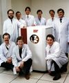
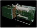
Future ETA Systems Mock up of ITASCA prototype: Product was not realized—ETA Systems was terminated by Control Data Corp.