File:26. Mark III IFF.jpg
Original file (2,474 × 1,940 pixels, file size: 1.73 MB, MIME type: image/jpeg)
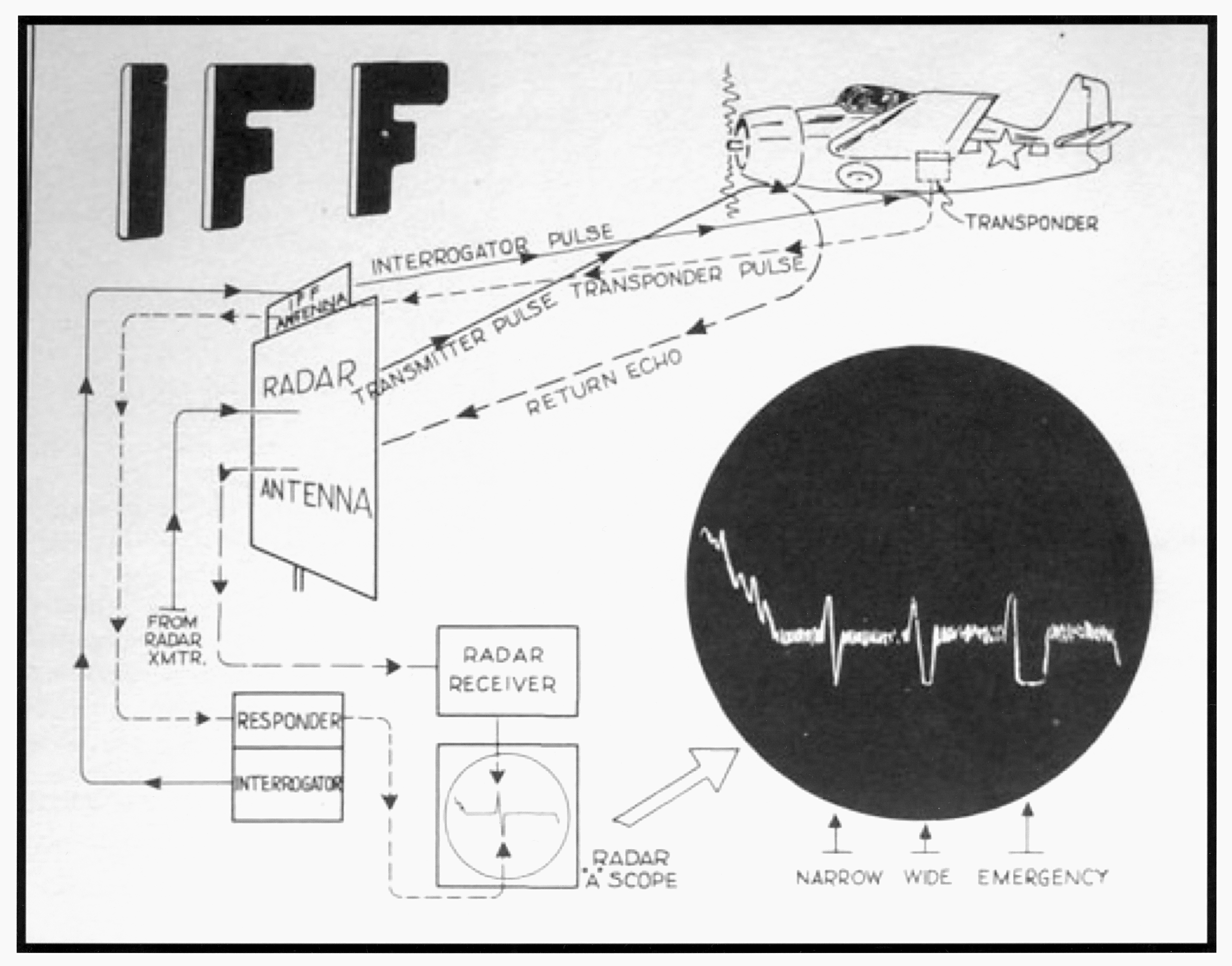
A depiction of the Mark III IFF system. The sharp upward points on this A-scope presentation represent the target return pips. The IFF response shows as a downward deflection immediately following the target pip. The transponder in the airplane could be set before a mission to return a sequence of three coded IFF responses a few seconds apart. Each response could be either a narrow or a wide response. There were six combinations for the coded responses that could be used to represent a prearranged code of the day, or to represent aircraft on different missions. The pilot could also throw a switch that caused a very wide response meaning an emergency condition. From RADEIGHT p. 64, Figure 53
File history
Click on a date/time to view the file as it appeared at that time.
| Date/Time | Thumbnail | Dimensions | User | Comment | |
|---|---|---|---|---|---|
| current | 18:10, 14 October 2015 | | 2,474 × 1,940 (1.73 MB) | Davidboslaugh (talk | contribs) | A depiction of the Mark III IFF system. The sharp upward points on this A-scope presentation represent the target return pips. The IFF response shows as a downward deflection immediately following the target pip. The transponder in the airplane could b... |
You cannot overwrite this file.
File usage
The following page uses this file: